特斯拉镇楼
1、什么是小车循迹?
将小车放在黑色跑道上面,小车沿着黑色跑道运动 → 循迹
黑色跑道

2、小车循迹基本原理
原理:
介绍原理之前,突然记起来,在电子爱好者上 做过 一个循迹小车的项目,那个介绍的相相当详细,和这个基本原理是一样的。
光敏电阻:光照作用下, 光敏电阻器的阻值下降。光敏接触(跑道)黑色线时,电阻上升
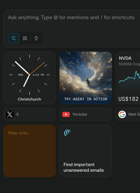
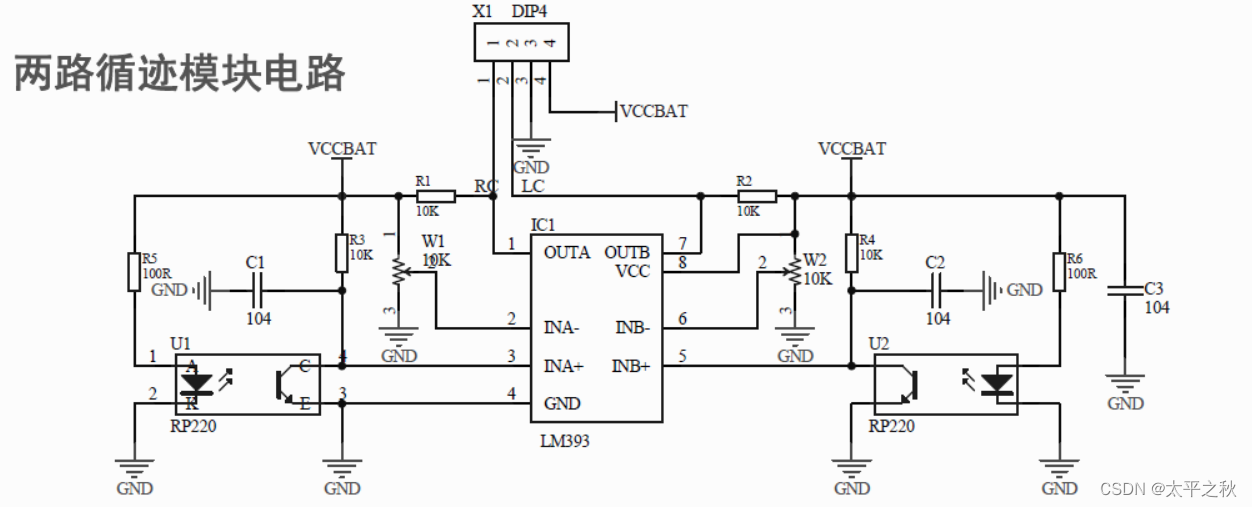
LM393 比较两路光敏电阻 R13 R14 的大小,不平衡时,控制压线侧电机停止,第二个电机工作,从而修正方向,使黑色跑道线保持在两轮之间。
硬件:
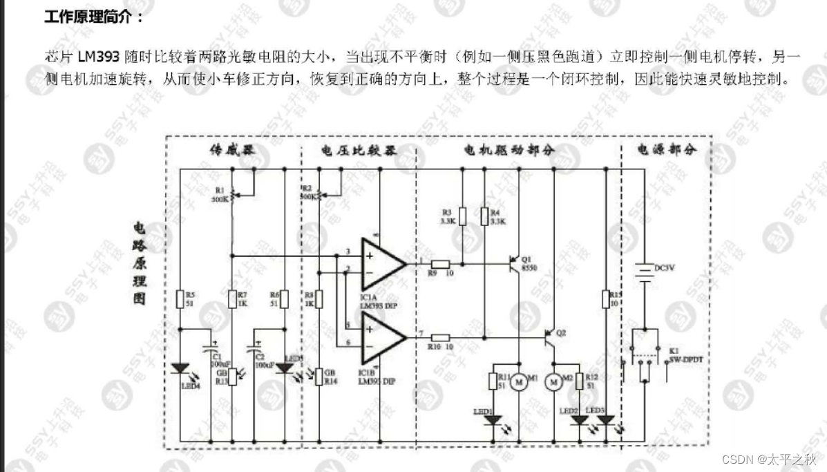
小车底板及附件:支撑,骨架,带四个车辆,前两轮为驱动轮;
可调电位器:10K ,用于调节循迹传感器模块的灵敏度
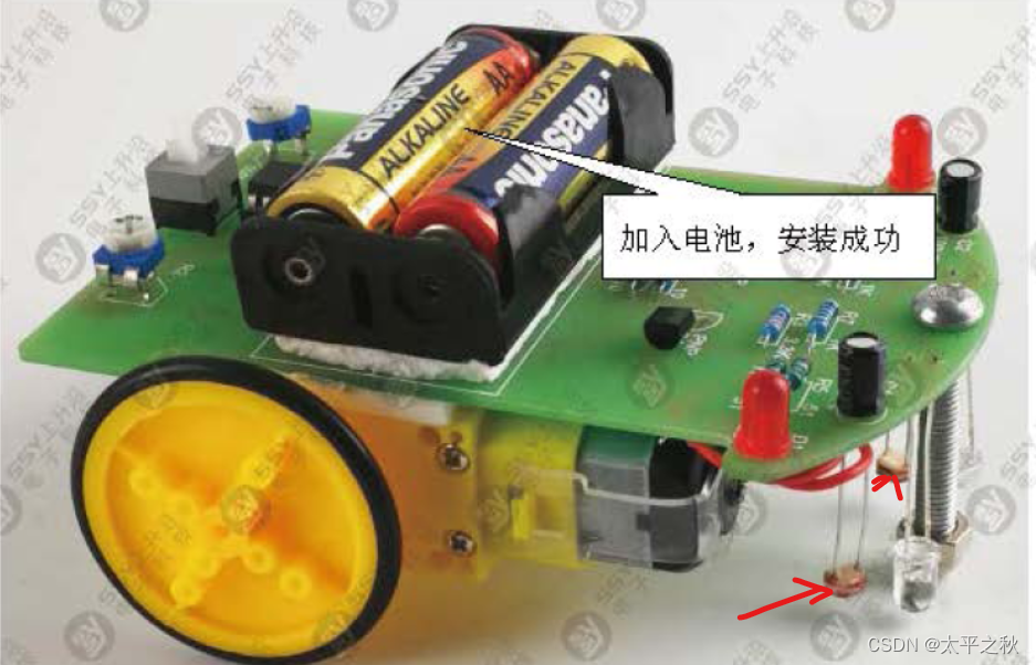
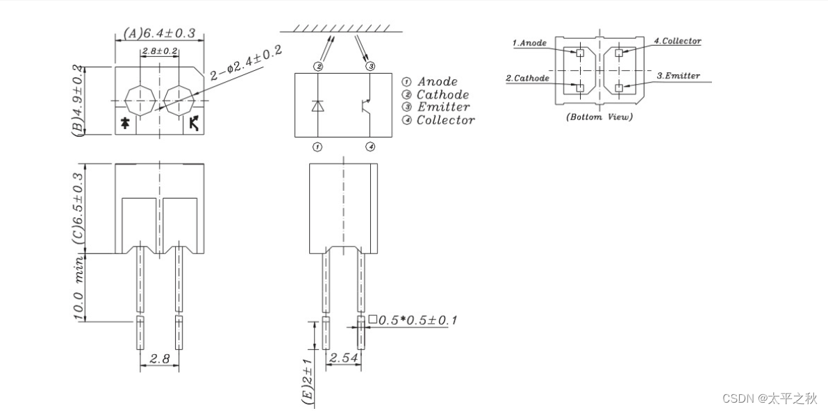
传感部件:2*反射式光电管 ,用于检测跑道black/white
四个引脚分别为:1 Anode 正极 2 cathode 负极 3 Emitter 发射极 4 collector 接收极
驱动:两个直流电机,作用为驱动车轮运动
电源:干电池
控制模块: LM393 & 单片机系统
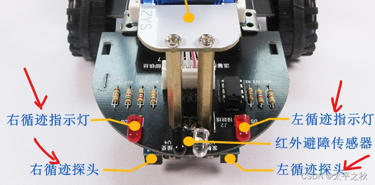
显示模块:LED ,循迹指示灯,当循迹探头检测到黑线,指示灯亮
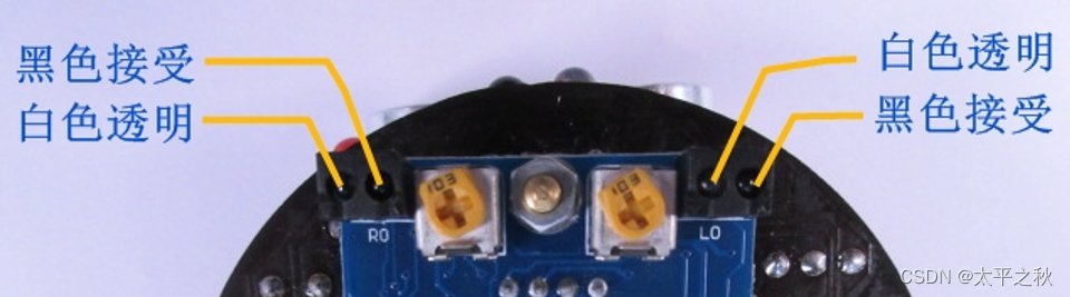
背面:白色是发射端,黑色是接受端
正面
电路图(基本原理与上面介绍的类似,只不过是把用LM393 检测的结果输出给 单片机)
3、小车循迹代码实现 和 分析
先来看主函数 main.c
 1
 2
 3
 4
 5
 6
 7
 8
 9
10
11
12
13
14
15
16
17
18
19
20
21
22
23
24
25
26
27
28
29
30
31
32
33
34
35
|
#include "stm32f10x.h"

#include "delay.h"

#include "motor.h"

#include "keysacn.h"

#include "IRSEARCH.h"

int main(void)

{

delay_init();

KEY_Init();

IRSearchInit();

TIM4_PWM_Init(7199,0);

STM32_brake(500);

keysacn();

while(1)

{

SearchRun();

}

}
|
初始化延时, delay_init();,在之前的内容已经谈论过啦,不赘述
初始化按键, KEY_Init(); 使用的是 GPIO 外设 ,设置和我的学习笔记0 让小灯亮起来类似
 1
 2
 3
 4
 5
 6
 7
 8
 9
10
11
12
13
14
15
16
17
18
19
20
21
22
23
|
void KEY_Init(void)

{

GPIO_InitTypeDef GPIO_InitStructure;

RCC_APB2PeriphClockCmd(RCC_APB2Periph_GPIOC,ENABLE);

GPIO_InitStructure.GPIO_Pin = GPIO_Pin_2;

GPIO_InitStructure.GPIO_Mode = GPIO_Mode_IPU;

GPIO_Init(GPIOC, &GPIO_InitStructure);

GPIO_InitStructure.GPIO_Pin = GPIO_Pin_3;

GPIO_InitStructure.GPIO_Mode = GPIO_Mode_Out_PP;

GPIO_InitStructure.GPIO_Speed = GPIO_Speed_50MHz;

GPIO_Init(GPIOC, &GPIO_InitStructure);

}
|
初始化探头,IRSearchInit(); PA7 PB0
 1
 2
 3
 4
 5
 6
 7
 8
 9
10
11
12
13
14
15
16
17
18
19
20
21
22
23
24
25
|
void IRSearchInit(void)

{

GPIO_InitTypeDef GPIO_InitStructure;

RCC_APB2PeriphClockCmd(RCC_APB2Periph_GPIOA|RCC_APB2Periph_GPIOB , ENABLE);

GPIO_InitStructure.GPIO_Pin = SEARCH_R_PIN;

GPIO_InitStructure.GPIO_Mode = GPIO_Mode_IPU;

GPIO_InitStructure.GPIO_Speed = GPIO_Speed_50MHz;

GPIO_Init(SEARCH_R_GPIO , &GPIO_InitStructure);

GPIO_InitStructure.GPIO_Pin = SEARCH_L_PIN;

GPIO_InitStructure.GPIO_Mode = GPIO_Mode_IPU;

GPIO_InitStructure.GPIO_Speed = GPIO_Speed_50MHz;

GPIO_Init(SEARCH_L_GPIO , &GPIO_InitStructure);

}
|
初始化 PWM 电机 配置,见学习笔记1 TIM4_PWM_Init(7199,0);
按键读取程序, keysacn(); 同时程序中加了一个蜂鸣器作为反馈声,被按下时蜂鸣器响
 1
 2
 3
 4
 5
 6
 7
 8
 9
10
11
12
13
14
15
16
17
18
19
20
21
22
23
24
25
26
27
28
29
30
31
32
33
34
35
36
37
38
39
40
41
42
43
|
void keysacn()

{

int val;

val=KEY;

while(!GPIO_ReadInputDataBit(GPIOC,GPIO_Pin_2))

{

val=KEY;

}

while(GPIO_ReadInputDataBit(GPIOC,GPIO_Pin_2))

{

delay_ms(10);

val=KEY;

if(val==1)

{

BEEP_SET;

while(!GPIO_ReadInputDataBit(GPIOC,GPIO_Pin_2))

BEEP_RESET;

}

else

BEEP_RESET;

}

}
|
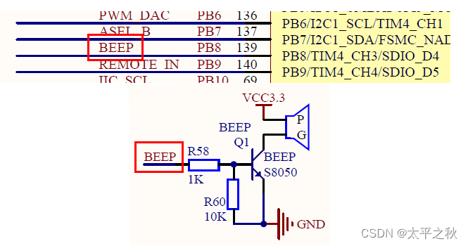
蜂鸣器定义函数:怎么让蜂鸣器响起来? 蜂鸣器定义为 PC3
 1
 2
 3
 4
 5
 6
 7
 8
 9
10
11
12
13
14
15
16
17
18
19
20
21
|
#ifndef __KEYSACN_H_

#define __KEYSACN_H_

#include "stm32f10x.h"

void KEY_Init(void);

void keysacn(void);

#define BEEP_PIN GPIO_Pin_3

#define BEEP_GPIO GPIOC

#define BEEP_SET GPIO_SetBits(BEEP_GPIO,BEEP_PIN)

#define BEEP_RESET GPIO_ResetBits(BEEP_GPIO,BEEP_PIN)

#define KEY GPIO_ReadInputDataBit(GPIOC,GPIO_Pin_2)

#endif
|
下图为示意,实际为 PC.3口为高电平时,蜂鸣器发声,为低电平时,不工作
while(1)
{
SearchRun();
}
SearchRun();
 1
 2
 3
 4
 5
 6
 7
 8
 9
10
11
12
13
14
15
16
17
18
19
20
21
22
23
24
25
26
27
28
29
30
31
32
33
34
35
36
37
38
39
40
41
42
43
44
45
|
void SearchRun(void)

{

if(SEARCH_L_IO == WHITE_AREA && SEARCH_R_IO == WHITE_AREA)

ctrl_comm = COMM_UP;

else if (SEARCH_L_IO == BLACK_AREA && SEARCH_R_IO == WHITE_AREA)

ctrl_comm = COMM_LEFT;

else if (SEARCH_R_IO == BLACK_AREA & SEARCH_L_IO == WHITE_AREA)

ctrl_comm = COMM_RIGHT;

else ctrl_comm = COMM_STOP;

if(ctrl_comm_last != ctrl_comm)

{

ctrl_comm_last = ctrl_comm;

switch(ctrl_comm)

{

case COMM_UP: STM32_run(50,10);break;

case COMM_DOWN: STM32_back(50,10);break;

case COMM_LEFT: STM32_Left(50,10);break;

case COMM_RIGHT: STM32_Right(50,10);break;

case COMM_STOP: STM32_brake(10);break;

default : break;

}

}

}
|